
Our Product
- ROLLERBRAKE™ pioneered the use of braking rollers in stopping belt runaways and reducing downtime.
- ROLLERBRAKE™ transforms the conveyor roll into a braking device.
- Braking is activated by friction between the belt and the stationary roller’s outer surface.
- Cylindrical roller bearings within the device act directly on the shaft generating immediate stopping force.
- The absolute strength of the 25mm and 30mm model is in excess of 400 Nm (SABS tested), which is used to determine the braking force of the braking force of the ROLLERBRAKE™ device.
- Manufactured to ISO 9000 quality standards and supplied to SABS-accredited manufacturers.
- ROLLERBRAKE™ is committed to cutting-edge innovation and improvement in our offerings to customers.
Since inception, we have continuously improved ROLLERBRAKE™ quality, power, and durability
WHAT IS THE ROLLERBRAKE™
- The ROLLERBRAKE™ is strong and simple.
- Almost frictionless operation.
- Each device is Zinc plated for corrosion protection.
- A rear lip seal is added to ensure brake internals and housing has additional protection.
- A rubber seal is also included to prevent the ingress of moisture and dirt into the brake and bearings.
- The ROLLERBRAKE™ is available in a fully enclosed HDPE unit.
- Manufactured for 25mm, 30mm, 40mm, 50mm and 60mm shaft sizes.
- ROLLERBRAKE™ has no effect on the normal operation of the conveyor roll.
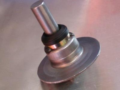
Complete Steel Assembly
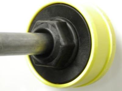
Complete HDPE Assembly
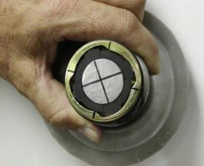
HOW THE ROLLERBRAKE™ WORKS
- When the ROLLERBRAKE™ has been installed and running in the normal direction, centrifugal forces ensure that the ROLLERBRAKE™ units run frictionless as the pin-bearings we use seats themselves in the highest point of the cam designed in the metal housing.
- The shaft ensures that the bearing remains stationary while the metal unit attached to the idler continues moving.
- When the belt snaps or the belt is switched off the cams designed within the ROLLERBRAKE™ metal unit cause friction on the pin bearings which are forced onto the shaft, braking the idler.
SIMULATED OPERATION WITH A 25mm STEEL UNIT

Free Running
Engaged
For any further technical information and/or test results please contact us directly.
ROLLERBRAKE™ IN THE FIELDThe required quantity of ROLLERBRAKE™ is calculated from the data captured on the Information Specification Sheet(ISS Download PDF) from which a suggested layout pattern is then formulated and provided. This Information Specification Sheet must be accurately completed and forwarded on to the relevant contract holder or approved manufacturer.
Coverage will vary under the following belt conditions:
|